
Handling Ethanol New Issues for Terminals
By: Kathy West
PFT-Alexander, Inc. Featured in International Liquid Terminals Association 2006 |
 |
Introduction
PFT-Alexander is a manufacturer’s Representative of Flow Measurement and Control Equipment. We have been around since 1958, and I have been involved with Flow Measurement for over 25 years.
PFT-Alexander is a “Full Service” company with 25 Technicians who are trained to repair the equipment we represent and the other options. This gives us a unique capability to see what happens to the equipment once it is in service. We are also the largest state licensed calibration company on the West Coast so we are continually assessing the performance of equipment in the applications I am here to discuss today. I hope the following information helps you as an update on what we have learned.
PFT-Alexander is a “Full Service” company with 25 Technicians who are trained to repair the equipment we represent and the other options. This gives us a unique capability to see what happens to the equipment once it is in service. We are also the largest state licensed calibration company on the West Coast so we are continually assessing the performance of equipment in the applications I am here to discuss today. I hope the following information helps you as an update on what we have learned.
Handling Ethanol & New Issues for Terminals
Then:
In the late 90’s, Ethanol re-surfaced as a possible oxygenate choice for the California Market. Several companies placed off rack wild stream blenders in the terminal tank farm to prepare, but MTBE was ultimately chosen and blended in the refinery and piped to the terminals until MTBE usage was banned. The companies who already had these blenders were ready and willing to accept Ethanol into the Terminals. The pros for this system were the limited disruption to the existing loading procedures. The Cons- If the system failed the rack could be down without blended product. The companies who had blenders proceeded to use them with “redundant” equipment & insure blended Product on the racks. The unique “growth” issue was known from past experience with blending on the East Coast and identified to be about 0.016%, considered not to be much of an issue.
Other companies looked at a complete re-do of their loading racks with the addition of Sophisticated Electronic Presets, meters and valves to sequentially load the product separately into the Delivery Truck in a layering process controlled by the Electronic Preset. This created the problem of pumping back retains or off spec loads going to trans mix since Ethanol blended product could no longer go back to usable storage but had to go to Transmix, a great loss of potential dollars sold.
One way this problem was rectified was by the conversion to ratio blend capability of the electronic presets – controlling both Gasoline product meters, valves and Ethanol meters and valves. This is costly due to the amount of equipment needed and the down time of the load rack for modifications. Some customers felt this change was warranted due to the losses incurred by off Spec and Transmix problems.
This rack modification included meters on the Gasoline product usually a 4” Turbine flow meter, 4” control valve and 2” Ethanol meter and control value. This design would give the electronic preset the control to open both product valves on the authorization of the control system. It would meter both products and control both valves allowing the blending to occur into the loading arm and on into the truck. These meter signals gave the volumes to the B.O.L. printer and the system for inventory control (The Pros) of this system; it was a good blend eliminating the risks associated with sequential blending (almost).
The Cons:
Due to the original specification in California of 5.7% Ethanol to Gasoline blend it was very difficult to control and maintain the product blend accuracies using 1.5” or 2” Turbines and valves on the small volumes of Ethanol. A typical 1.5” Turbine flow of
13-130 gpm standard at a published accuracy of ± 0.25%.
This low flow rate caused additional problems trying to hold control of an already tight blend parameter. This is one reason the systems were being proven often to try to hold or tighten up this critical blend quantity.
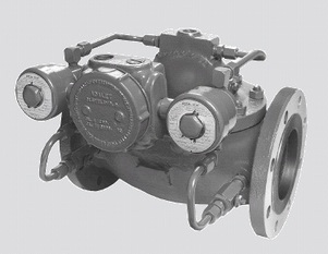
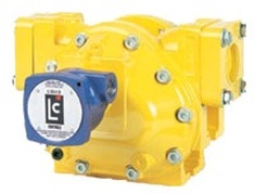
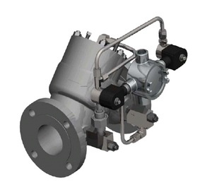
FMC Smith Diaphragm Operated Control Valve
What have we learned
Now:
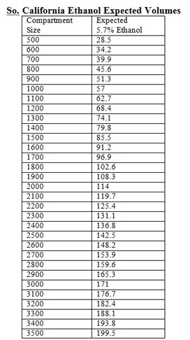
Since both 1.5” and 2” meters were trying to control the flow rate with a 2” diaphragm control valve, it was very hard if not impossible to blend through out the full blend cycle, causing the necessity to adjust how a blend was arrived at. In perfect lab conditions, you might be able to get it but since a globe style diaphragm valve operates by line pressure and the loading rack has inconsistent pressures due to all the different compartments loading at the same time this was found to be intolerable from a quality control stand point. Consider the following volumes to see how little 5.7% really is when loading it into a compartment and trying to blend consistently throughout the load.
Since both 1.5” and 2” meters were trying to control the flow rate with a 2” diaphragm control valve, it was very hard if not impossible to blend through out the full blend cycle, causing the necessity to adjust how a blend was arrived at. In perfect lab conditions, you might be able to get it but since a globe style diaphragm valve operates by line pressure and the loading rack has inconsistent pressures due to all the different compartments loading at the same time this was found to be intolerable from a quality control stand point. Consider the following volumes to see how little 5.7% really is when loading it into a compartment and trying to blend consistently throughout the load.
Corrected to 6B
With the introduction of Ethanol came the new Gasoline’s and Gasoline blends. Here are some of the things we have found on new Gasoline handling. In the desulphurization process the Gasoline has become drier (sulfur acted as a lubricant) this drier product has been found to act differently with the existing handling equipment. We have found the necessity to prove the Turbine flow meters more often since calibration is truly the testing of equipment to indicate wear or change in performance. This is a very good way to check on your equipments performance. We actually purchased new types of proving equipment with sophisticated electronics to allow us to see and track from one proving to another for the meters true deviation. When we saw a meter factor shift (the prior calibrated number) to a greater or smaller number we investigated and found some very surprising things.
When a typical Turbine meter is manufactured it has a stainless steel internal with rotor or blade design to float in the product fluid by use of Journal or Ball Bearings. The meter internals in the past would only deviate if something hit a blade or the bearings simply wore out. But as you can see, the new Gasoline products were affecting the meter internals in a whole new way. The main thing a Turbine cannot tolerate is a coating. It disrupts the balance and performance of the blade design.
See FMC Technologies – Turbine Meters for Liquid Measurement (Truck Loading) Technical Paper # 25 - TP02002, reference viscosity coating issues.
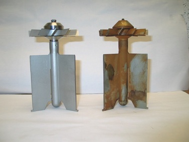
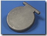
New Internal vs. Gasoline Exposed Internal
These pictures show what we found on inspection of some Turbine meter internals on (neat) 100% Gasoline no exposure of Ethanol.
When we removed the “suspect” internal it looked pretty good no indication of blade distortion but it had a sticky/slimy type of feeling with almost a gritty sensation when you rubbed your fingers together. When the internal was placed out of the product and while a new internal was replaced the suspect internal began to dry, the longer it was exposed to the air, the more the “chocolate milk” type of coating started to appear. Once it was identified we started looking for this trying to identify what it was. It was not isolated to a single customer and it was a finding we could not ignore. When we tried to rinse it off, it looked okay on some but on others it looked almost etched. The washing on some internals did no good, it came back anyway.
With these findings, it became clear that on all future product meters we must recommend the return to P.D. Positive Displacement designs to insure the best performance where the coating would not hurt the meters performance, but actually increase its consistency.
Over the last few years the industry of meter manufacturers has kept producing Positive Displacement Meters with tried and true performance. They have improved the capability and reliability while giving the upgraded meter a high pulse resolution output required for sophisticated electronic control systems. These outputs have been designed to eliminate as many moving parts as possible while giving reliable single or dual outputs. With the focus turning to P.D. meters, new installations started using a more cost effective single case design. But with the issues of temperature causing pressure swings and product expansion and contraction, it is time to rethink this application. API Chapter 5, Section 2- Measurement of Liquid by Displacement Meters references variations in flow rate, viscosity, temperature and pressure 5.2.8.6.1 states “The physical dimensions of the meter will also change as a result of the expansion or contraction of its housing under pressure. The use of double-case meters prevents this problem.”
5.2.8.6.1 Variations in Pressure
If the pressure of the liquid when it is metered varies from the pressure that existed during proving, the relative volume of the liquid will change as a result of its compressibility. The potential for error increases in proportion to the magnitude of the difference between the proving and operating conditions. For greatest accuracy, the meter should be proved at the operating conditions (see Chapter 4 and Chapter 12).
The physical dimensions of the meter will also change as a result of the expansion or contraction of its housing under pressure. The use of double-case meters prevents this problem.
Since we have issues with blending now and the possibility of even higher vapor pressures in the future it is our recommendation for your best option to look at the new high breed electronic pulse output positive displacement double case design options.
The following designs show the difference.
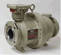 Brodie Meter BiRotor Plus - Housing: Brodie Double Case Carbon Steel |
 Liquid Controls M-60 - Housing Two Case Steel Case |
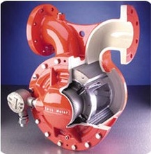
FMC Smith Meter Model Prime 4 Single Case Meter
Ethanol Findings:
As we’ve shown on Gasoline, there are issues also with Ethanol. Ethanol is very dry. It is manufactured by a cold or hot process and comes from many sources. We have found some Ethanol’s leave a “sticky” residue when exposed to air and left to dry. But in all cases it is very dry to handle. This residue leaves a white powder like coating on the Turbine meters and when handled in the neat 100% state on the API couplers. The Turbine meter internals when removed look almost milky then when left to air dry, it’s a rough powder. It does not wash off easily and even leaves an etched surface rough to the touch
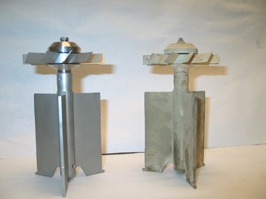
New Internal vs. Ethanol Exposed Internal
Since we have the same concerns of coating with any Turbine meter it is now recommended to use a P.D. Positive Displacement flow meter for this application also.
Another advantage to using the Positive Displacement flow meter is the ability to get down to very low flow measurement. Flow rate -3-60gpm. ± 0.25% accuracy. You still want to look for a Custody Transfer Certified meter with the best accuracy and repeatability available including the same high resolution output signal as the product P.D. meter feeding your electronic control system.
Again, in this design you want to look to a meter designated for this service, preferably double case design.
Enraf Fluid Technology - Stainless Steel Oval Gear Meters - 1 1/2" & 2" - Certified Custody Transfer Ethanol Meter
Now What Have We Learned With Ethanol?
This coating is throughout the industry and the Sulfate levels have been investigated as a possible source of clogging problems experienced in the automobile industry very similar to what we are experiencing.
ASTM analysis of Sulfate and Chloride are two other analytes that are monitored in a number of ASTM standards currently Sulfate is not part of the D4806 Fuel Standard but Chloride is.
A new specification applied to the ASTM international spec for Ethanol D4806 would put the maximum level of sulfates in the renewable fuel at 4 parts per million (ppm). This proposed standard was approved in December 2005 by ASTM’s Gasoline Subcommittee and went to its D02 Subcommittee on Petroleum Products and Lubricants for final approval hopefully by June 2006.
This 4ppm spec is greater then the original 1ppm request and we hope this will alleviate our coating issues. Since no one has identified the actual “root cause” we will continue to monitor the performance of the equipment exposed to Ethanol and Ethanol blends. In the test labs two proposed Sulfate analytical methods are being compared the evaporative IC method for Chloride and Sulfate and a lead potentiometer titration method for just Sulfate. These tests could finally answer what we are dealing with and help solve the coating problems.
Valve Findings
If you are blending and want to have consistent performance across the entire load, the valve choice also becomes a critical path. Your first option is a hydraulic actuated ball valve. This gives you a separate source of power not effected by outside product pressure swings for smooth liner operation, control and full range blending. Your second option would be the use of a hydraulic operated piston control valve that has a linear design to insure smooth blends and is less affected by pressure swings. Electric actuated valves are large and typically have slow response speed, pneumatic actuated while quick have clean/dry air problems and corrosion can really effect valve performance. Globe style diaphragm valves have low end performance problems from pressure swings.
Brodie BV788 Linear Piston Control Valve
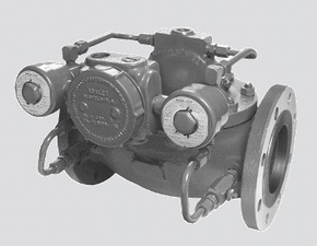
FMC Smith Diaphragm Operated Non-Linear Control Valve
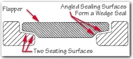
When handling Alcohol 100% or Ethanol another important issue we have found is the use of a high quality check valves. In the past poor quality checks have caused problems maintaining a good blend. You should look for an unobstructed large bore for maximum flow, a single piece design flapper and shaft, high quality Inconel X750 spring material, and AFLAS seal material. To ensure safety a Fire Safe API6FA and 6FD design is recommended. In California where emissions are a huge issue the retainerless design eliminates external holes or shaft leak points. All these features are again important because of the vapor pressures and coating and aggressive nature of the new products.
What to Look for in Check Valves
HY-GRADE's flapper and shaft are designed as an integral component with large diameter shafts to provide strength at a critical location. In contrast, typical check valves have multiple components which are assembled together using bushings, nuts, bolts, and hinge pins. Over time these multiple components tend to come apart leading to valve failure. HY-GRADE's integral flapper and shaft design has a long and proven history of providing reliable service in the harshest of applications.
|
 |
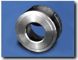 |
HY-GRADE's Large Unobstructed Bore provides maximum flow capacity with extremely low pressure drops. The unobstructed bore also allows HY-GRADE check valves to be used in slurry, high consistency or abrasive applications.
|
|
HY-GRADE developed the WedgeSealTM metal-to-metal sealing. As shown in Figure 1, the WedgeSealTM has two seating surfaces which are machined at slight angles. As a result, positive shut off is obtained due to the wedging action of the sealing surfaces. Note, the sealing surfaces are machined only at slight angles to prevent the valve from "sticking" in the closed position in high back pressure applications. The WedgeSealTM technology makes HY-GRADE metal seated check valves excellent for both low and high pressure applications.
|
 |
About Ethanol
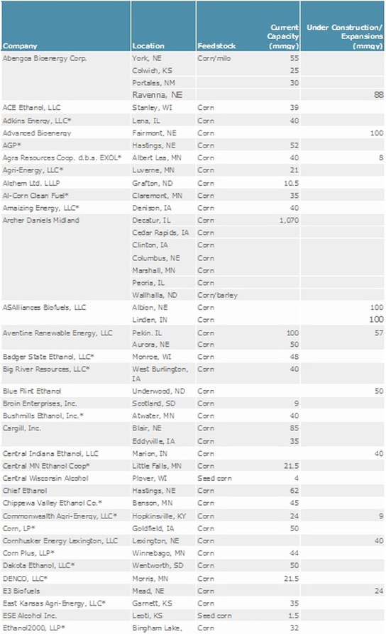
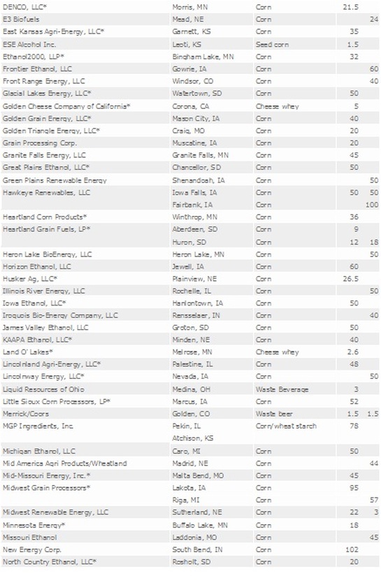
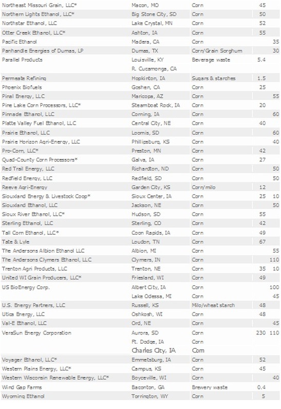
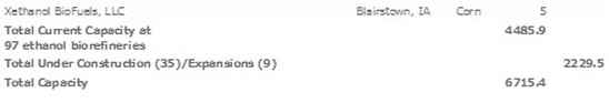
What have we learned, not all Ethanol is created the same way! And we have now found out it comes from many sources. We have U.S. production from all types of sources such as corn (US’s largest producer), sugarcane, beets, cheese waste, agriculture waste, brewery “wet mush”, off spec or out of date beer, wine, spirits and fruit juices just to mention a few. I have discussed applications where farmer co-ops are looking at re-capturing the after harvest typical lost product and in place of burning or tilling back into the soil, they process it into alcohol for sale. This shows an ever increasing market of Ethanol production from all types of sources. This list shows just how many there already are with huge plans for expansion.
New Design Options and Recommendations
We have identified gains and losses across the racks with customers continually looking at the meters proving more often and trying to identify exactly what is happening. These findings and changes in the meters were not the only issues that have been identified.
Originally when Ethanol was first introduced as a component to Gasoline on the East Coast the curiosity of its Exothermic and Endothermic (Expansion and contraction) when combined with Gasoline was identified. The number generally used for this was a growth rate of 0.16% on 10% Ethanol into Gasoline, something the industry was not concerned about.
But there have been a lot of changes to the delivery rates, and the actual Gasoline specifications particularly in California where we have special Gasoline blends. This expansion and contraction is so inconsistent a true correction table has yet to be developed since pressure, temperature and delivery rate seem to impact this growth factor. Most customers use Table 6B as a reference at this time. But customers were still trying to identify why they were having losses and yet seeing gains at some point. They have identified a rise in complaints from their customers on volume discrepancies, why? One customer proceeded to run a series of tests checking the rack flow meters with Small volume provers and Volumetric provers at different times of the day at different pressures and flow rates and discovered a startling fact the growth was not at a 0.16% but at 0.38%. A Huge number and this could explain a lot. To be sure the customer had these findings verified in a lab and considered what this meant to the terminal, and the product delivery design.
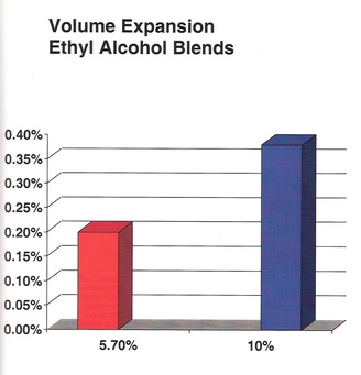
Presently if the growth is this large and we are blending the products sequentially into the delivery truck the terminal is giving that growth away into the truck to the station. The same is true with Ratio blends when we are adding the Ethanol into the line and the product into the line each through a dedicated meter the line into the truck and the truck itself are experiencing the growth past the meter and giving it away.
Each 2,000 gallon load with a 10% blend of Ethanol as typical throughout the US and has a growth once in the truck of 0.38% or 7.6 gallons. If that product sold for $1.50 per gallon (not today’s prices) each 2,000 gallon load compartment is losing $11.40. A typical truck delivery is loaded with 6,500 gallons a loss of $37.05 every time a truck goes out the gate.
How can we capture that loss? This option has been identified as “Side Stream” blending. You have to rethink your loading rack design to move your Ethanol injection upstream from your product meter. This placement should be as far as possible away from that delivery meter.
Existing Sequential Options
To eliminate the option of Sequential blending except for Midgrade blends, place your Ethanol into your product lines away from the load rack point of Sequential delivery, this will be the least disruptive to your existing loading.
You can place an off rack Ethanol Blender feeding into your product lines thus giving you pre blended and already expanded product to Sequentially Blend or deliver straight into the delivery truck.
You can place an off rack Ethanol Blender feeding into your product lines thus giving you pre blended and already expanded product to Sequentially Blend or deliver straight into the delivery truck.
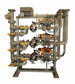
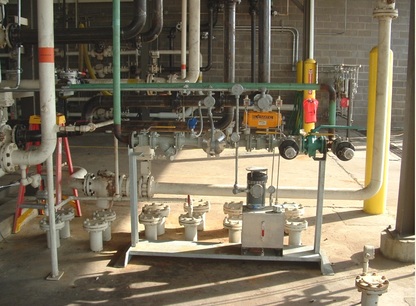
Enraf Prefabricated Enthanol Blender
Existing Ratio Blending Sites
If you have added 2” Ethanol on your load rack and it is piped into a header line already being fed product you have the option of moving that Ethanol injection farther upstream of the Gasoline product meter. This will give you two things. The growth (% dependent upon how far up stream you go) also it will leave you a single point of Custody Transfer, allowing you the option to eliminate some of the Custody Transfer Weights and Measures requirements for the 2” Ethanol equipment. But remember if you still have Turbines this might not be an option due to the other performance issues with this design of meter.
Another option if you added a prefabricated “rack” of 2” equipment you could move it farther away to gain the maximum amount of growth available.
Another option if you added a prefabricated “rack” of 2” equipment you could move it farther away to gain the maximum amount of growth available.
Enraf Prefabricated Bay Blender with Microblend Controller
Enraf Prefabricated Skid Slave Blender
The cost to redesign your loading rack by moving existing equipment can be paid for by your gains dependent upon your thru-put. In most cases very quickly.
Pros:
Capture growth and not give money away. Identify loses and help eliminate. Have more stable product getting to the customers helping eliminate nuisance calls. Cut your Custody Transfer meter proving costs (if you have accurate reliable meters).
Cons:
Some disruption to loading while changes are being made. Some Electronic Preset Loading Equipment Systems are not capable of the Side Stream capability to calculate this type of blending. The major systems are very aware of these issues and can help you identify if your system has the proper capabilities. All large newer systems do.
Remember the original customers I referenced, the first ones to put off rack blenders into their facilities? Those customers are the luckiest ones of all. They didn’t know it but they were capturing the growth and making the profit all this time. They couldn’t figure out why they had gains (remember they only expected a 0.16% growth) and all along they have had a great performing system without even realizing it.
Enraf Wild Stream Blender P&ID
Gains & Losses
Inventory control issues have also risen on the “gains/losses” hunt for product.
It has been identified that just installing the new radar style level equipment with Custody Transfer Accuracy will not answer all your needs. Yes the improvements of accurate measurement on products that have expansion and contraction issues such as Ethanol is important it has now been found temperature changes are also a critical factor.
On Gasoline, Enraf has found that 1/8” of level in accuracy on a 75’ diameter by 32’ tall tank can mean 344 gallons. But what is really amazing is what a 1°F temperature error can be 695 gallons of lost product.
Thermal Expansion Error Table
The chart below is a list of possible errors that caused from thermal expansion of the liquid hydrocarbon product due to incorrect temperature
readings of 1 degree Fahrenheit.
readings of 1 degree Fahrenheit.
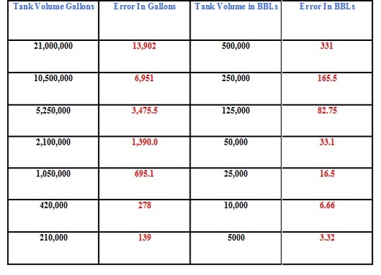
(Calculation from approximate average VCF of 0.000662 for an API gravity of 55 through 50 to 100 degree Fahrenheit range bases on information from API table 6B.
On testing Gasoline products and Ethanol with a portable level and temperature test unit (with accuracy to Custody Transfer Spec) the range of temperature on a Gasoline product or Ethanol tank can be surprising.
API has recently recognized this and is now recommending 9 temperature points on a 50’ tank being taken.
Another reason to actually test your tank level and temperature is to verify the “seasonal” changes as they occur to insure your accounting for any swings.
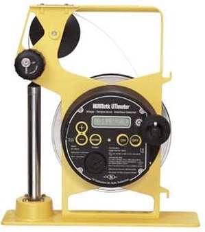
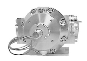
Enraf HERMetic UTImeter Otex - Portable Liquid Level Gauge and Temperature Verification Unit
E85 - Coming to a Terminal Near You
This new fuel a blend of 15% Gasoline to 85% Ethanol needs to be recognized as having the same issues we are seeing today with higher pressure issues and possibly coating it is a good candidate for the Double Case Positive Displacement Flow Meter. The volumes might be reversed in the blends we presently have of 5-10% Ethanol to 90-95% Gasoline but you can blend it with the same technologies.
Since it is a purer form at 85% Ethanol the issue of maintenance and diaphragm “dry out” where the diaphragm in a globe style control valve fails due to long exposure to 85% Ethanol losing flexibility or tearing out at flex points. Diaphragm valves are dependent on pressure for control so an aggressive maintenance check on the valves in this service is warranted.
Vapor recovery units and systems should also be reviewed due to the increase in vapors for the proper Emissions Standard Operations and Performance Regulations.
Options Now Recommended
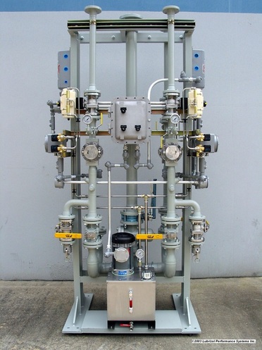
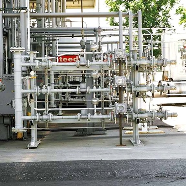
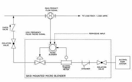
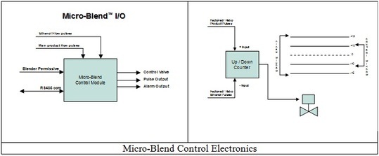
Since customers outside of California had the luxury of learning from our experiences. Some manufacturers decided to redefine their systems in an effort to eliminate some of these problems. Many terminal operators chose to have the total blend capability of Ratio blending and pipe the Ethanol into a dedicated skid unit. This small blender or Micro Blender was designed to arrive at a Terminal completely prefabricated and tested; it could be placed on the end of a loading rack and all wiring and piping done and in place with a simple tie in to the existing system, eliminating the disruption of the rack. This would allow the entire system to remain the same with the Ethanol Microblender having a dedicated P.D. Positive Displacement flow meter for each Gasoline arm to independently blend Ethanol into that single product Gasoline arm by using the existing Gasoline meter signal into the blender microprocessor where the configurable recipe and the hydraulic control valve operation is handled. This gives each arm total independence and if you lost one blend position the others were still functioning with the use of P.D. Meters and hyd. actuated ball valves this design cured the issue of the very low flow rates. With the RS485 communications capability the microblend controller could send the actual volume of Gasoline and the actual volume of Ethanol per load of desired for accurate inventory control and quality control check points.
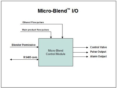
Typical Microblend Control for Ethanol Blending
If a customer had a sophisticated control system with side stream capability this simple blender rack design could be placed downstream of the product meters the blender electronic control would then be done by the control system with the prefabricated blender acting as a slave only to the control system eliminating redundant electronics.
These types of systems and the original tank farm wild stream blending of Ethanol into the Gasoline product on the way to the loading rack will insure the capture of the growth insuring better loss and gain inventory controls.
These types of systems and the original tank farm wild stream blending of Ethanol into the Gasoline product on the way to the loading rack will insure the capture of the growth insuring better loss and gain inventory controls.
Loading & Offloading Ethanol
We are finding more and more sites have concerns with accuracy and the best technology to safely handle Ethanol.
In ship off loading you need to identify if you will be handling Alcohol 100% neat either from your production or receiving from another source. If you are you must apply for a DSP (Distilled Spirits Permit) and be authorized and monitored by the Alcohol Tax Trade Bureau. If you are planning on using this product as Petroleum Gasoline Additive it must be de-natured to the ASTM D4806 standard for Gasoline. You should also consider additional capability for anticorrosion additive. A system to achieve this has been devised that assures the proper blending of the Gasoline denature and the anticorrosion inhibitor with an automated system to custody transfer accuracy and complete communications capability to interface to a computer for volume reconciliation and reporting. At the ship off load point an Ultrasonic Flow Meter with a 10:1 turndown and no moving parts measures the Alcohol being off loaded this meter is equipped with a pulse output that is wired to a prefabricated Denature Skid that comes equipped with a pump motor, starter, meter and valves with an Electronic Blender Microprocessor Module that accepts the Ultrasonic flow meter pulse and controls the Gasoline denaturing stream from the pump then the meter and valves to the injection point where it is pacing the blend. The electronics is programming via RS485 or by a hand held controller to your predetermined denature percentage. If you desire anticorrosion inhibitor the same Ultrasonic flow meter signal could be sent to an additional injector and inject the quantity you desire at the same time at a different point, while keeping a totalized volume of Ethanol and Anticorrosive being injected available to the system via RS485 or locally for your mandated DSP permit requirements. This system design has passed Alcohol Tax Trade Bureau inspections and is presently used in California.
In ship off loading you need to identify if you will be handling Alcohol 100% neat either from your production or receiving from another source. If you are you must apply for a DSP (Distilled Spirits Permit) and be authorized and monitored by the Alcohol Tax Trade Bureau. If you are planning on using this product as Petroleum Gasoline Additive it must be de-natured to the ASTM D4806 standard for Gasoline. You should also consider additional capability for anticorrosion additive. A system to achieve this has been devised that assures the proper blending of the Gasoline denature and the anticorrosion inhibitor with an automated system to custody transfer accuracy and complete communications capability to interface to a computer for volume reconciliation and reporting. At the ship off load point an Ultrasonic Flow Meter with a 10:1 turndown and no moving parts measures the Alcohol being off loaded this meter is equipped with a pulse output that is wired to a prefabricated Denature Skid that comes equipped with a pump motor, starter, meter and valves with an Electronic Blender Microprocessor Module that accepts the Ultrasonic flow meter pulse and controls the Gasoline denaturing stream from the pump then the meter and valves to the injection point where it is pacing the blend. The electronics is programming via RS485 or by a hand held controller to your predetermined denature percentage. If you desire anticorrosion inhibitor the same Ultrasonic flow meter signal could be sent to an additional injector and inject the quantity you desire at the same time at a different point, while keeping a totalized volume of Ethanol and Anticorrosive being injected available to the system via RS485 or locally for your mandated DSP permit requirements. This system design has passed Alcohol Tax Trade Bureau inspections and is presently used in California.
Enraf Typical High Capacity Blend Skid
Status of BioDiesel in California 2006
In 2005, three producers made almost 7 million gallons of BioDiesel by end of 2006 that number is expected to reach 30 million gallons. Since the sale of BioDiesel is still only allowed through registered user groups that hold a variance it is still a small market.
Since the Governor of California signed into law in 2005 the allowance for the use of B20 for the municipal fleet use and defined BioDiesel in terms of the National Standard ASTM 6571.1 AB1007. This requires all agencies with a stake in BioDiesel to develop a plan for its retail sale starting in 2007. With fuel prices what they are today and all the media attention focused on the alternative fuels market a huge ground swell of interest is pushing for these products getting to market as soon as possible.
Ultra Low Sulfur Diesel (ULSD) will be sold by July 2006, and it’s believed car makers are starting to certify BioDiesel for use on some models.
The blends being looked at today are B10, B20 and in the manufacture B100, Blend Stock.
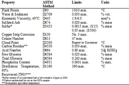
Requirements for BioDiesel (B100) Blend Stock as Listed in ASTM D6751-03
Since BioDiesel (B100) Blend Stock has been recognized by the U.S. Department of Energy’s Clean Cities Program as the fastest growing alternative fuel in the U.S., it is being reviewed as a fleet fuel of the future by 2010 or before.
Here are the differences between Diesel/BioDiesel
Here are the differences between Diesel/BioDiesel
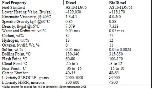
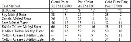
Selected Properties of Typical No. 2 Diesel and BioDiesel Fuels
Handling BioDiesel
It’s new and always with any new product we see issues. We have seen several “BioDiesel” options. These are Standard Diesel with Ethanol and Additives, a new BioDiesel Blend including a special additive and Water, Fat and Grease (the French Fry) BioDiesel and its additives.
All of these and many more products have one thing in common; they need to be handled across the local loading terminal’s load rack to get into the distribution chain. The BioDiesel present specifications ASTM D6751 sets the standards for BioDiesel Fuel when produced. But with any new product we have found issues that will need to be addressed.
Like the coating issues found in Ethanol, BioDiesel like Standard petroleum Diesel appears to have a microbial growth that creates a black scum and sludge, again something lab tests and analysis will have to address.
But this again points out the need to use the P.D. Positive Displacement flow meters to insure this does not cause additional problems with the measurement and insure a good blend.
To complete this task, a BioDiesel Blender is designed much the same as an Ethanol blender with all the capability to take the different percentage (%) components and blend them into the loading arm per a pre determined recipe.
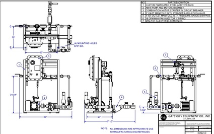
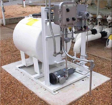
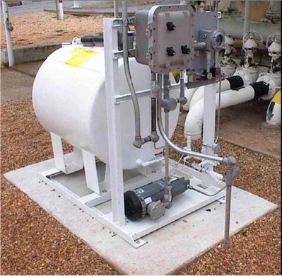
This BioDiesel blender shown was designed to actually fit through a doorway to be installed inside a “Blending Building” to control the temperature of the products to help maintain a good consistent product blend. Some BioDiesels have very tight temperature parameters, it can become more viscous in colder environments until blended or it has to be heated to be blended properly. In tank mixers and temperature control tank heaters might also be necessary on installation.
Prefabricated Rack Mounted BioDiesel Blender
This typical rack mounted outdoor BioDiesel Blender, blends the preheated mixture directly into the existing load arm.
Additive Level Verification Monitoring
Again the issue of good level with temperature monitoring on your BioDiesel tanks will insure the best performance.

Tote & Small Tank Level Control Enraf Opti System
If you are blending and need to add small amounts of additional Biocide additives to detour microbial growth the use of an additive injector system designed to inject directly into the BioDiesel tank on receipt will give you accurate measurement of the actual BioDiesel Volume, and the quantity of additive per gallon from the injector RS485 Communications capable electronics, thus insuring your inventory control accounting. This could give you a record by batch of all components.
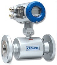
Ultrasonic Pacing Flow Meter
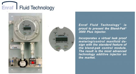
Enraf Blend-Pak 3000 Plus Additive Injector
Because most “BioDiesels” actually use an Ultra Low Sulfur Diesel base and blend in other components as well to achieve their special blend. This option could also be accomplished at the loading rack with the use of a Micro Blender feeding a percentage of the special blend component or components into the existing Diesel loading arm. If the system were capable you could have an existing ULSD Ultra Low Sulfur Diesel arm do both duties with a separate recipe initializing a permissive signal to the blender to operate only as the driver requested by recipe on the electronic preset. This could be accomplished by blending in BioDiesel Blend component until the low flow shut down than allowing only the Low Sulfur Diesel to flush the line and “lay the arm down” or fill with only Low Sulfur Diesel for the next truck load.
This option could be accomplished by the use of Microblender Electronics in conjunction with a control system.
This option could be accomplished by the use of Microblender Electronics in conjunction with a control system.
Enraf Prefabricated Blender
This design would give any existing load rack the option of joining into the BioDiesel market with a minimum disruption to existing loading.
Mechanical Delivery System
If you are a customer with a simple loading need, you can utilize a single product loading system. This would allow you the option of preblending all of your components into a “day” tank where a mechanical system could then fill a truck via hose or loading arm, print a ticket and give you another option to get your product to market. This equipment could come prefabricated on a portable skid allowing you to place it near your Diesel product tank, and a portable tote or tank of your BioDiesel product. The Diesel delivery line would have a meter in place this signal volume would go into the blender electronics where the blend ratio would control and record the BioDiesel Product delivery through another meter and valve giving you a preblended dedicated line to your point of sale meter into the vehicle. This system could allow for additional additive injection also using a pulser on the P.D. Delivery meter to an additive injection system and tote assembly.
Prefabricated Mechanical Loading System
Red Dyed Diesel/BioDiesel
The dying of diesel has been around for a number of years and we plan to offer the same type of equipment for ULSD and BioDiesel we presently use.
We have found using a Mag Drive Pump and motor assembly with Vitec coated Stainless Steele internals has helped to improve pump life in Red Dye Applications. Original problems arose with the nature of dye. It starts out as a dry product and was originally cut or blended with Xylene as a carrier. Because the dye was continually venting off, it had a tendency to become more and more viscous. If it was spilled and dried it would reactivate when in contact with hydrocarbon and water. Like rain water, with its high concentrations, this could get into sumps, waste water treatment and other hard to control/clean points. Very costly to clean up.
Now the industry has an oil base carrier that eliminates the Xylene and offers a more stable product, helping the life of the equipment and clean up is much easier. It is still nasty stuff to work with, but it has improved.
Enraf Fluid Technology Systems Dye-Pak Systems is designed for injecting dye. This system is easily adapted to handle any low dosage additive applications.
Safety & Biodiesel
USDOE studies show BioDiesel is safe to handle; Flash point 260 degree +. But the misconception seems to come when the product is mixed with diesel. In the past, Diesel was thought to be easy to handle as compared to Gasoline. But now that the BioDiesel is being blended into Ultra Low Sulfur Diesel, additional issues are of concern.
Recently, ASTM has been asked to adopt a minimum spec for conductivity in the US. This request looks to add an electrical conductivity requirement to existing diesel fuel standards. The proposal calls for ULSD to contain a minimum of 50 pico siemens per meter (pS/m).
The issue because ULSD has low electrical conductivity due to reduced sulfur content, the fuel is prone to static charge build-up (and subsequent discharge) when added at fast flow rates to tanks where Gasoline vapors from a previous Gasoline load are present. In a worst case scenario, enough of a static charge could cause a tank or a truck to explode, say industry sources. This “Worse Case Scenario” has happened.
Switch loading has been an issue for some time but it has now become even more critical with ULSD.
Our concern is if a customer does not have this knowledge and receives a truck previously loaded with Gasoline and begins a BioDiesel blend with non-additized ULSD, an accident could occur.
If a facility is planning on handling ULSD we recommend an additive injection system for ASA- Anti Static Additive prior to and handling to insure safety.
Another consideration is the API recommendation for grounding and overfill protection. These systems ensure the vehicle once connected by a WOGA (Western Oil and Gas Association) plug connection will be prevented from overfilling a truck utilizing the onboard truck sensors, once contact is made at this sensor in a compartment the control system would shut down delivery by removing the pump permissive or closing the delivery valve (ESD- Emergency Shut Down).
The industry offers grounding and overfill combination boxes with an override switch option if desired. The box is then wired to a junction box where the plug is attached for truck monitoring.
 |
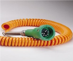 |
Civacon Combination Grounding and Overfill Protection Monitor - WOGA Plug and Cord
Ultra Low Sulfur Diesel - New Requirements
ASTM has updated D975 the standard specification for Diesel fuel. This incorporates the lubricity requirement, for fuels with insufficient lubricity performance that can cause wear to fuel injectors and other equipment. D975-046 establishes the testing required to meet these new standards. If a customer finds the need for additional lubricity additive a pre-fabricated system is recommended this pump and injection system can be sized for either tank injection or Load Rack delivery to one or more Diesel Arms.
Ultra Low Sulfur Diesel (ULSD) Lubricity Additive Injection System
In Summary
Our experience has shown for handling, you consider the following:
- Use Positive Displacement flow meters in Gasoline products including Ethanol.
- Use Hydraulic operated Ball Valves or Piston Style Linear Control Valves in place of Globe Style Diaphragm Operated Design.
- Consider Automated Prefabricated Blenders.
- Place the Ethanol Blend point as far as possible away from the custody transfer delivery meter to take advantage of the growth and for additional profits.
- Check your level but monitor your temperature. Temperature can really be a problem.
- Look at your Ethanol usage if you are planning on Denaturing Alcohol you will need a DSP permit and process to denature and capture your volumes handled for record keeping.
- Be sure your check valves are high quality to insure proper closure and hold for blending.
- E85 can be blended using the same technology but you might need additional maintenance on diaphragm control valves and vapor emissions review.
- BioDiesel Blending can be blended with the same equipment as presently doing Ethanol.
- BioDiesel might require the addition of special additives for performance.
- Reminder BioDiesel must be handled and additized with concerns for static discharge.
- Yes, you can use the same systems for Red Dye / BioDiesel as we use for Diesel today.
- All Fuel Delivery Systems including Diesel and BioDiesel should consider grounding and overfill control and monitoring.
- Ultralow Sulfur Diesel Lubricity standards have changed. This might require some additional Lubricity Additive to be injected either at the Rack or into the tank.
References
- API
- Chapter 5- Measurement Standards Liquid Metering
- Section 2- Measurement of Liquid Hydrocarbons by Displacement Meters
- Ethanol Producer Magazine- March 2006
- Industry calls Denatured Ethanol Analysis
- Ethanol Producer Magazine- April 2006
- Dr. Jerry King- Denatured Ethanol Analysis MidWest Laboratories, Inc.
- BioDiesel Magazine- February 2006
- Ron Kotrba- Compatible by Design
- OPisalerts
- 03/23/06- Conductivity Specifications
- BioDiesel Council of California
- Enraf Fluid Technology
- Brodie Meter Co., LLC
- Liquid Controls
- ENR Magazine- February 2006
- BioDiesel is Popular
- RFA- Renewable Fuels Association
- Hygrade- Victor Tumer- Check Valve Performance
- U.S. Department of Energy 2004
- BioDiesel Handling and Use Guidelines
- PFT-Alexander Service, Inc.
- Chris Conway, Prover Operations
- FMC/Smith Meter Company


