

Introduction
Biodiesel’s U.S. surge in popularity can be linked directly to the Energy Conservation and Reauthorization Act (ECRA) in 1998, which allows tax advantages for B20 use in certain alternative fuel fleets. This language amendment and tax advantage upgrade came on the heels of
the Energy Policy Act of 1992, which defined biodiesel as an alternative fuel and allowed tax advantages with the use of the more expensive and more demanding B100 fuel.1
Biodiesel has inherent advantages, the use of which provides far-reaching advances to the environment. Its use lessens dependence on
petroleum, reduces greenhouse gas emissions by as much as 41% if produced from existing crops, and it can reduce tailpipe emissions due to the decrease in nitrogen oxide and sulfur dioxide2.
The chemical nature of biodiesel allows it to be blended with any kind of distillate or diesel fuel. This includes light fuels such as jet
fuel, kerosene, No. 1 diesel or military fuel (JP8, JP5), normal diesel fuel such as No. 2 diesel, Ultra Low Sulfur Diesel (ULSD) for diesel engines or gas turbines, and heating oil for boilers or home heating.
Once biodiesel is blended thoroughly with diesel fuel, it stays together as one fuel and does not separate over time, assuming the fuel is
maintained at temperatures above its cloud point. Once blended, B20 and lower blends should be treated exactly like conventional
petroleum.
The newest specification ASTM International D6751, released in October 2008, sets the standards for biodiesel when it is produced, but as with
any fuel, issues needing immediate attention may arise when handling and storing it in order to maintain the integrity of the fuel and the storage materials. The most common challenges with ASTM-grade biofuels and how to resolve them are examined in this white paper, as is how to choose the proper equipment to maintain quality fuel and for cost-efficient long-term maintenance.
Temperature
A critical issue for manufacturers and distributors of biodiesel is temperature control or low temperature operability. Biodiesel can become gelatinous at low temperatures, causing a host of equipment problems.
The cloud point, or low temperature at which solid crystals form, can range depending on the plant or animal base, however, the recommendation remains the same that it should be stored 5° - 10°F higher than cloud point.3 Low temperatures also adversely affect B100’s pour point, which is the lowest temperature at which the fuel will flow for pumping. See Table 1 for the cloud and pour points for various methyl ester sources.
For these reasons, constant temperature control and the ability to add low-temperature flow additives or heat the fuel are essential to a biodiesel operation.

Product Availability and Inventory Management
Facilities lacking good measurement control risk giving product away. In fact, studies have shown that using highly accurate measurement equipment for tank gauging can pay for itself, and the need to know the true product temperature at all points in the delivery process can help facilities stay profitable.
Consider findings4 that show if a typical tank is reading just 1” off its level there will be a loss in the facility’s accounting and inventory control numbers. However, if a tank is 1° off, it can be off by twice the volume.
Temperature is a critical function in any true measurement of available product. The best practice is to have the most accurate level – preferably custody transfer accuracy – for level gauges and volume. The next most important feature is to have a secondary, independent high-level alarm in order to meet state and federal requirements for spill prevention. And finally, always be aware of the most accurate product temperature in your tanks from top to bottom.
It is common for temperature to vary on the outside wall of a tank, but it also can vary when it is being mixed, which can become a critical factor if you have a product that must be maintained at a temperature range for proper blending and quality control. Knowing exactly how much product you have at all times is important, but knowing the temperature of that product is critical.
Storage and Material Compatibility
It is best to store the base product biodiesel B100 as a B20 or some kind of blend as soon as possible regardless of the season since B100 does not store as well as blended products do.
Common diesel and ULSD products use nitril or buna-N compounds that are not suitable for biodiesel. Polypropylene, polyvinyl and tygon materials are also particularly vulnerable to B100 issues. For example, they will degrade, soften or seep through some hoses, gaskets and seal/elastometers or they will attack glues and plastics with prolonged exposure.
Brass, bronze, copper, lead, tin and zinc may accelerate the oxidation of diesel and biodiesel fuels and potentially create fuel insolubles (sediments or suspended matter) or gels and salts when reacted with some fuel components. Avoid all lead solders and zinc linings, as well as copper pipes, brass regulators and copper fittings typically used in older water systems.
Recommended equipment is made of stainless steel, carbon steel or aluminum.
Deterring Growth
Like standard petroleum diesel, biodiesel appears to have a growth that creates a black scum and sludge. Small amounts of biocide or herbicide may be added to deter microbial growth.
An additive injected directly into the biodiesel tank on receipt will provide accurate measurement of the biodiesel and the quantity of additive from the injector system. RS485 communications and electronics ensure inventory control accounting and can provide a record by batch of all components.
If your process is delivering into a tank, you have the option of installing a non-custody ultrasonic flowmeter with no moving parts. This signals the delivered volume of B100 to the biocide additive injector electronics to pace in the desired volume per gallon.
Identify Your Biodiesel
Since all basic materials are called B100 it is important to discern exactly what the biodiesel you are working with is processed from. Soy, canola, lard, tallow, palm, coconut, rape seed, jatropha fruit and other oils are typically used as the bases for biodiesel fuel.
Biofuel cloud point and pour point properties are severe at 32°F and a homogenous blend of biodiesel is key to quality. At this time B100 is being blended into fuel at 1% - 5%, 10% - 20% with future 30%, 40%, 50% and 100% blends.
In the United States, ASTM D6751 includes specific test methods to check for biodiesel quality and ensure the delivered product meets the required standards as a biodiesel fuel. There are various changes in the new standards but one recurring issue is the need to control the blends and maintain quality.
If the biodiesel is manufactured to strict standards, where it is closely controlled on a by-batch basis, the next step is to ensure the downstream handling is just as controlled on a by-load basis. The equipment capability will ensure or break down the very quality control standards being pushed for today.
Measurement and Control
Biodiesel facilities can profit from good measurement and control in a number of areas of the production process: measurement of received oils, oil in process, control of steam and condensate, methanol and catalyst, volumes of glycerin for resale and wash water, and control of the final biodiesel production into the storage tanks.
From the storage tanks the base product will be sold into the distribution chain either neat or blended into another finished fuel per required specifications, perhaps with additional additives to meet quality control standards. Downstream, therefore, the emphasis is on accurate blending and custody transfer control.
The potential for entrained solids and the viscosity of biodiesel points to the need to use Positive Displacement (PD) flowmeters to prevent measurement problems and to ensure a good blend. PD flowmeters have been proven to give high accuracy and repeatability on the loading rack. A PD meter’s design can offer an accuracy rating of +/- 0.075% with repeatability numbers at +/- 0.01% as compared to a typical turbine flowmeter’s rating of +/- 0.15%. This is a very important improvement when looking at consistent blending.
If the temperature and pressure of the liquid when it is metered varies from the pressure that existed during proving, the relative volume of the liquid will change as a result of its compressibility. The potential for error at this point increases in proportion to the magnitude of the difference between the proving and operating conditions.
For greatest accuracy, the meter should be proved at the operating conditions. Since biofuel is often heated to overcome cold-flow properties, this becomes a critical issue. The physical dimensions of the meter will also change as a result of the expansion or contraction of its housing under pressure and temperature. The use of double-case meters helps prevent this problem. Since issues can arise from blending now, and there is the possibility of even higher blend viscosities in the future, the use of a custody transfer PD meter is the best option.
Control Valves
Two-stage control valves are a critical choice in the decision-making process for a delivery system, as the valve is the control point to accurately deliver the requested volume on demand, and it ensures safety for low-flow start and stop.
Also, in case of emergency, the valve is the final stop on the way to the truck for overfill prevention. If you are blending, the design of the valve can definitely impact the accuracy of the blend. A linear valve design leads to the smoothest, most accurate operation.
The first option is a hydraulic-actuated ball valve, which gives a separate source of power not affected by outside product pressure swings for smooth linear operation, control and full-range blending.
The second option is a hydraulic-operated piston control valve that typically can operate up to 500 SSU in viscosity with few problems. This has a linear design to ensure smooth blends and is less affected by pressure swings.
Other non-linear options tend to be less effective. Electric-actuated valves are large and typically have a slow response speed. Pneumatic-actuated valves, although fast, have clean/dry air problems and corrosion can substantially affect valve performance. Globe-style diaphragm valves have low-end performance problems for pressure swings, and are typically limited to no more than 200 SSU viscosity. In addition, diaphragm material and wear are concerns.
Regardless of valve design, to ensure the proper speed of operation on any control valve, verify the viscosity range being handled and the limitations of the valve restrictions. To protect and save the control valve, always place a spool after the valve prior to the loading arm base swivel or hose connection. This protects the valve holding back the product from spilling in the case of a pull-away accident.
Good quality check valves ensure the product blends and help maintain consistency of raw products until called for. Therefore, when choosing a check valve, make sure the flapper and shaft are designed as an integral component with large diameter shafts to provide strength at a critical location.
In contrast, typical check valves have multiple components assembled using bushings, nuts, bolts and hinge pins. Over time these multiple components tend to come apart, leading to valve failure. Large unobstructed bore provides maximum flow capacity with extremely low pressure drops. The unobstructed bore also allows check valves to be used in heavy viscosities or abrasive applications.
Loading and Blending
Load rack blending is an important element contributing to the success of an operation. It reduces dependence on multiple storage tanks, which helps maintain flexibility due to the ability to load multiple products from each load arm. Therefore, a blending skid design must take into consideration the following issues for adding a biodiesel blending capability to the load rack:
· The need for a small footprint blender
· The special requirements for accurate volume measurement of biodiesel
· Temperature compensation for accurate reconciliation
· The facilitation of simple system proving and calibration
· The varied communication interfaces into the existing load rack
· The flexibility of multiple blend ratios
The blending of B100 base stock with another product can be done using one of the following three methods:
1) Using a blender, when you are going for more than a 5% blend, mounted by the rack with the different blend components metered and controlled on demand by a recipe – as called for by an electronic preset. This option gives you the most flexibility with the least amount of cost.
2) Using a high-capacity injector to have access to 1% - 5% blend rates operating in the same way as the traditional gasoline additive injector designs. It offers the desired small injection of diesel into the biofuel for tax consideration and has an accurate record of both the diesel added and the biofuel product delivered on a by-batch basis. Another option is to have the injector be a slave to the existing preset or control system.
3) Placing another meter on the rack, sized specifically to deliver the volume of additional product with the B100 to achieve the called-for recipe. This design limits flexibility to the delivery flow rate that the fixed single meter is capable of handling.
In the case of a preset design (option No. 1 above), the additive or blend ratio is controlled through a recipe or multiple recipes and a report generated by load on the quantities delivered of all products mixed. This would be a good choice in the case of several different small quantities being blended into the loading rack ULSD arm, to achieve a cocktail blend that is homogenous throughout the entire product load.
If you do not use your control system to control this feature, you can instead use microprocessor electronics that can accept the volume of B100 from the delivering product meter and inject the ULSD percentage of additive as desired while keeping a record of all components available. This also allows the control module to respond as programmed to alarms protecting your blend quality. If your blend gets far enough off, the microprocessor controller will sound an alarm and shut down an off-spec load. This can happen if you run out of a blend component or if there is a mechanical failure.
Some biodiesel blenders are designed to fit through a doorway to be installed inside a blending building in order to control the temperature of the products and help maintain a good, consistent product blend. Some biodiesels have very tight temperature parameters, as they can become more viscous in colder environments until blended, or they may need to be heated to be blended properly. In-tank mixers and temperature control tank heaters might also be necessary on installation.
Of course, more important than anything is the need for seamless integration of an additive injection or blending system so as to ensure accurate blend ratios, extended equipment life and cost efficiencies across the board.
This means being able to interface with a multitude of third-party equipment at the load rack, including current terminal equipment and new developments; receive a flowmeter pulse from an obsolete mechanical counter; and communicate with the latest terminal automation systems.
And finally, the application solution should take into consideration any peripheral equipment such as additive off-loading pump skids, storage tanks, booster pumps, containerized units and portable injection equipment.
Safety
Biodiesel typically contains less than 15 parts per million (ppm) of sulfur, though biodiesel producers that exceed 15 ppm sulfur are now required to reduce sulfur levels to meet U.S. federal regulations. However, sulfur acts as a lubricant, which means removing it also reduces lubricity, leading to safety issues.
Recently, there have been calls in the U.S. for the adoption of a minimum spec for conductivity, which would add an electrical conductivity requirement to existing ULSD fuel standards of a minimum of 50 pico Siemens per meter. This issue of low electrical conductivity due to reduced sulfur content means ULSD is prone to static charge buildup (and subsequent discharge) when handled at fast flow rates, particularly to tanks where gasoline vapors from previous gasoline loads are present. In the worst case scenario, enough of a static charge could cause a tank or truck to explode. Industry sources say this “switch loading” issue has been a problem for some time, but with the introduction of ULSD realize that it has special handling requirements.
Previously, No. 2 diesel had a flash point (the lowest temperature at which vapors will ignite in test conditions) of 60° - 80°C. Now ULSD has a flash point of 130°C, while biodiesel originally listed at 100° - 170°C. The ASTM is looking at a 200°C flash point that coincides with the National Fire Protection Association as a non-hazardous rating.
If a facility were manufacturing B100, a non-hazardous rating could be safe for a non-grounded loading specification. But that is often not the case since many manufacturers of biodiesel also want to move into the distribution of blended diesel/biodiesel products. If a facility without knowledge of the special handling requirements of ULSD received a truck previously loaded with gasoline and began a biodiesel blend with non-additised ULSD, an accident could occur.
Conclusion
By following proven practices from the existing fueling industry and applying them to biodiesel handling, facilities can have confidence in a quality product delivered in a safe manner with accurate inventory controls. Important factors leading to the achievement of the best practices listed in this paper are a facility’s equipment choice and continuous testing programs.
Table 2. Tips for Handling Biodiesel
· Use PD flowmeters
· Use hydraulic operated ball valves or piston style linear control valves in place of globe-style diaphragm operated design. Always check the viscosity rating of the valve choice.
· Consider automated prefabricated blenders as the best cost/quality option for full-range blending.
· Be sure to have a homogeneous blend for product stability quality.
· Be sure that check valves are high-quality single-piece design with full port flow.
· Biodiesel can be blended with the same equipment presently used for blending ethanol and red dye.
· Biodiesel may require special biocide or herbicide additives to ensure quality.
· Biodiesel must be handled with concerns for safety.
· Biodiesel cannot be handled through copper, bronze or brass due to oxidation and lead corrosion issues. Never use Buna N or Nitril elastometers or hoses.
Honeywell Biodiesel Solutions
Honeywell brings a wealth of experience and solutions to the biodiesel market. Through leadership in the petrochemicals and refining markets, Honeywell has expertise in the automation of process units required for making biodiesel required for blending and storing.
Honeywell offers a full automation solution for biodiesel plants with scalable offerings for process control, process optimization, plant safety, fire and gas detection, wireless instrumentation, tank gauging, truck loading and more. Honeywell works with technology licensors, engineering contractors and operating companies to develop the right solution for every company.
Honeywell offers global resources and unique capabilities for this dynamic market including:
· Main Automation Contractor capability incorporating solutions from Honeywell’s PKS Advantage, Enraf and Analytics portfolios
· Cost-effective automation solutions addressing wireless, plant safety, and corrosion detection and prevention
· Packaged automation solutions to bring your process to market up to 9 months faster
· Minimized product giveaway (typical savings of $1M per year)
· Operator training to minimize disruptions and incidents
Products specific to the topics discussed in this paper include the following:
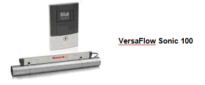
VersaFlow Clamp-on Ultrasonic Flowmeter: This non-custody transfer flow measurement product offers immediate startup, continuity and long-term reliability, with measurement that can be taken anywhere. The clamp-on flowmeter, with its robust industrial construction and regreasing concept, provides a revolutionary solution for easy handling. Benefits include reduced installation cost and improved performance, as well as low service and maintenance costs.
Honeywell offers a full automation solution for biodiesel plants with scalable offerings for process control, process optimization, plant safety, fire and gas detection, wireless instrumentation, tank gauging, truck loading and more. Honeywell works with technology licensors, engineering contractors and operating companies to develop the right solution for every company.
Honeywell offers global resources and unique capabilities for this dynamic market including:
· Main Automation Contractor capability incorporating solutions from Honeywell’s PKS Advantage, Enraf and Analytics portfolios
· Cost-effective automation solutions addressing wireless, plant safety, and corrosion detection and prevention
· Packaged automation solutions to bring your process to market up to 9 months faster
· Minimized product giveaway (typical savings of $1M per year)
· Operator training to minimize disruptions and incidents
Products specific to the topics discussed in this paper include the following:
VersaFlow Clamp-on Ultrasonic Flowmeter: This non-custody transfer flow measurement product offers immediate startup, continuity and long-term reliability, with measurement that can be taken anywhere. The clamp-on flowmeter, with its robust industrial construction and regreasing concept, provides a revolutionary solution for easy handling. Benefits include reduced installation cost and improved performance, as well as low service and maintenance costs.
Blend Pak or Mini-Pak Additive Injection Systems: With more than 35 years of experience and 60,000 additive injectors installed worldwide, Honeywell Enraf offers custom solutions for every conceivable additive injection application for any array of requirements. These solutions have been developed to maximize accuracy, reliability and functionality, and minimize the cost of implementation.
There are five important components in a quality petroleum terminal additive injection system:
1. Additive injection method – metered flow
2. Additive injection electronic controller – accurate real-time control, configurable alarm reporting, RS485 communications
3. Pump systems – local and remote control, sequencing dual redundancy available, temperature, pressure and flow monitoring
4. Tank or tote supply storage – accessories for handling additives, including level and spill containment options
5. Load rack interface – extended I/O, multiple communications ports, batching options, denature solutions that meet reporting requirements and standalone capability
If any of these components are incorrectly selected the result will be a marginal injection system and one that is not ready for future growth.
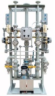
MicroBlender V.2 or Multi-Stream Blender: Blending applications – either the MicroBlender for single-stream applications or the Multi-Stream Blender for multiple-stream or multiple-product applications – are the continuous combining of two or more products to a predetermined specification during a standard flow process. The end result of these blenders, which use the latest microprocessor technology, is a smooth installation, accurate blend ratios and extended equipment life.
Honeywell Enraf blending systems include advanced functionality such as electronic remote configuration, and standard offerings such as multiple-target blend percentages, user-definable alarm outputs, quick calibration connections and clean arm flushing capability. An exclusively engineered slotted V-ball single-piston actuated control valve can achieve highly accurate linear control across the complete blend range. Microprocessor controllers are extensively configurable for automatic isolation valves and hydraulic power-paks for optimum ease of integration.
Honeywell Enraf blending systems include advanced functionality such as electronic remote configuration, and standard offerings such as multiple-target blend percentages, user-definable alarm outputs, quick calibration connections and clean arm flushing capability. An exclusively engineered slotted V-ball single-piston actuated control valve can achieve highly accurate linear control across the complete blend range. Microprocessor controllers are extensively configurable for automatic isolation valves and hydraulic power-paks for optimum ease of integration.
SYNCROTRAK® Small Volume Flow Prover: This product meets the most stringent accuracy requirements for meter proving: a precision, smooth bore cylinder and measurement piston, which contains an integral bypass valve to minimize disturbance to flow streams. During proving runs the piston is released from the return system allowing the piston to follow the flow stream unaided. The result is a minimum effect on the flow stream providing unequalled accuracy and precision. Sealing integrity is provided by PTFE-filled seals (no other elastomers), giving unrivaled fluid compatibility.
This flow prover has a constant displaced volume of 100% regardless of meter location, and contains no hydraulic or pneumatic features, which assures constant proving results with repeatability equal to or exceeding 0.02%. It also is the pre-eminent choice for all flowmeter types, including PD, turbine, coriolis and ultrasonic.
SmartRadar FlexLine: This tank gauging system uses radar technology and signal equipment, promises quick installation, seamless communication, reliable measuring under all conditions, trouble-free service and operation, unprecedented levels of accuracy and security, and above all, cost control. The latest tank gauging system from Honeywell Enraf, SmartRadar FlexLine’s modular design and accessories enable integration with virtually all tank inventory management systems, with synchronization performed via the new FlexConn architecture.

Servo Gauge 854 XTG or 854 ATG: Honeywell Enraf servo tank gauging inventory control systems are based on open platforms and feature modular construction, easy installation and simple maintenance to deliver optimized measurement performance in any environment. Intelligent software drives the microprocessor-controlled tank level gauges’ instrument functions, filtering out possible imperfections to optimize measurement accuracy.
The heart of the Honeywell Enraf servo gauging system is a highly accurate and advanced force transducer, which continuously measures the apparent weight of the displacer and eventually actuates the servo controller when the storage tank is emptied.
Besides measuring the liquid level, Honeywell Enraf’s 854 XTG and 854 ATG gauges can also be used for measuring the interface level between two liquids. For this purpose, the servo motor, actuated by an interface command, lowers the displacer to the point where its apparent weight corresponds to the programmed interface setpoint of the second liquid. This functionality is particularly useful to determine the sediment level or the interface level between water and tank liquid or between two liquids.
VITO MRT: The VITO family for temperature and water-bottom measurement, together with the Enraf tank gauges, is the ultimate answer for inventory control needs. As one of the first available products measuring the average product temperature in tank gauging applications, Multiple Resistance Temperature (MRTs) devices consist of multiple resistor elements each having a different length. Depending on the liquid level measured by the level gauge, the longest completely submerged element is selected to represent the average temperature of your stored product.
The VITO MRT advances the opportunity to upgrade tank gauging equipment without replacing all temperature elements. Its intrinsically safe signals comply with all major safety requirements for use in hazardous areas.
Alarm Scout: This tool easily measures the extent of alarm and control system events on a daily basis and automatically collects performance data on system alarms and events, returning e-mail reports to stakeholders. Recent requirements for independent secondary high-level alarm monitoring can be achieved by using the Alarm Scout equipment.
Alarm Scout reveals alarms that continually demand operator attention, alerting users that a remedy may be in order. This results in time-efficient improvements in the overall safety of an operating environment. In addition, use the Alarm Scout analysis capability for one-page Alarm Performance Benchmark Reports that summarize the overall alarm performance for particular operator consoles or areas of responsibility.
Alarm Scout requires minimal installation and its software components include the data collector, which packages the event data into a file for transfer to the Honeywell server, and the secure Scout Express utility, which performs the actual transfer and checks for data integrity. Reports are returned to customers via e-mail and require no additional infrastructure.
Entis XL: This new platform offers a low-cost inventory management solution for terminals with up to 50 tanks. It combines a broad range of inventory management functions with advanced automation and control of tank instrumentation. Entis XL uses the scanning and calculating modules, and with the Smartlink fieldbus, users have the flexibility to incorporate future expansions easily.
To reduce engineering and maintenance costs, Entis XL offers an unmatched engineering potential and flexibility for all tank utility applications. It is an open environment with interfaces to enable connections to the field and to control, MIS and ERP systems.
SmartLine: For smaller tanks, instead of Entis XL, the best option may be SmartLine equipment featuring choices in economical free space radar technology or guided wave designs.
References
1. National Renewable Energy Laboratory (NREL) Publication TP-540-43672. “Biodiesel Handling and Use Guide: Fourth Edition,” (U.S. Department of Energy, Revised January 2009.) Page 7.
2. NREL Pub. TP-540-43672. “Biodiesel Handling and Use Guide: Fourth Edition,” (U.S. Department of Energy, Revised January 2009.) Page 8.
3. NREL Pub. TP-540-43672. “Biodiesel Handling and Use Guide: Fourth Edition,” (U.S. Department of Energy, Revised January 2009.) Page 17.
4. Calculations prepared by Honeywell Enraf per ISO and OIML standards.


